Hex to 7-Segment Decoder
Easily decode hexadecimal (hex) values into 7-segment display patterns using this Hex to 7-Segment Decoder. Whether you’re designing digital circuits, simulating microcontrollers, or learning digital electronics, this tool helps visualize how hexadecimal numbers are represented on a 7-segment LED display.
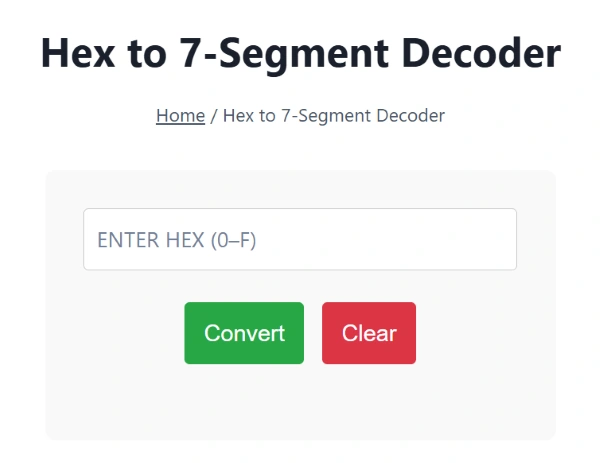
The hex to 7 segment decoder image is shown below:

What Is a 7-Segment Display?
A 7-segment display is a digital output device commonly used in:
- Calculators
- Digital clocks
- Embedded systems
- Microcontroller projects
It consists of seven individual LEDs (labeled a–g) arranged in a figure-8 configuration. These segments are selectively turned on/off to display digits (0–9) and some hexadecimal letters (A–F).
Want to better understand the base values? Try our Hex to Decimal Converter for detailed breakdowns.
How Does Hex to 7-Segment Decoding Work?
Hexadecimal values (0–F) correspond to standard 7-segment patterns:
| Hex | Display | Segments (a-g) |
|---|---|---|
| 0 | 0 | a, b, c, d, e, f |
| 1 | 1 | b, c |
| 2 | 2 | a, b, d, e, g |
| … | … | … |
| A | A | a, b, c, e, f, g |
| F | F | a, e, f, g |
The decoder interprets your hex input and returns the 7-segment LED segment status or bit pattern needed to light up each segment.
You can convert your hexadecimal into binary first using our Hex to Binary Converter for a clearer view of the bit layout.
Common Bit Encodings in 7-Segment Decoders
In electronics and embedded systems, 7-segment displays are often controlled using 8-bit codes where each bit represents a segment:
Bit Order: g f e d c b a
Example: 0x3F → 0011 1111 → Displays "0"
Some microcontroller kits use common anode or common cathode logic, which may invert these bit patterns.
Use our Hex Bitwise Calculator to toggle or mask individual bits as needed.
Features of Our Hex to 7-Segment Decoder Tool
✅ Supports 0–F hexadecimal input
✅ Displays active segments (a–g)
✅ Outputs 7-segment bit pattern
✅ Visual 7-segment LED simulation
✅ Works for common cathode/anode logic
✅ No signup required – instant, fast, mobile-friendly
Use Cases for Hex to 7-Segment Decoding
- Microcontroller (e.g., Arduino, PIC, STM32) programming
- Display driver IC interfacing (e.g., 74LS47, CD4511)
- FPGA logic design
- Testing and debugging hardware outputs
- Digital electronics education
If you’re designing logic for embedded outputs, this tool helps simulate and verify segment activation before deploying on hardware.
To reverse engineer a 7-segment pattern into its hexadecimal value, use the Binary to Hex Converter.
FAQs – Hex to 7-Segment Decoder
Q1: Can this tool handle lowercase hex (a–f)?
Yes, the tool supports both uppercase and lowercase hex characters from 0 to F.
Q2: Does it support custom encoding formats?
It uses standard 7-segment encodings for educational and common IC simulations. For advanced bit mapping, use the Hex Bitwise Calculator.
Q3: Can I simulate both common cathode and anode?
Yes! Toggle between inverted or normal logic to see both common cathode and common anode behavior.
